Complex Geometry Machining: A Buyer’s Guide to Multi-Axis Precision Parts
Not every part is a block with holes in it. Impellers, turbine housings, gimbal mounts, and organic-shaped brackets have curved surfaces, undercuts, and compound angles that a standard 3-axis mill simply can’t reach in one setup. Complex geometry machining is what closes that gap — but it also separates shops that genuinely run multi-axis equipment from ones that quote it and subcontract the hard features out. This guide covers what complex geometry actually requires in terms of equipment, material behavior, and inspection, so engineers can specify it correctly the first time.
What Makes a Part “Complex Geometry” in CNC Machining
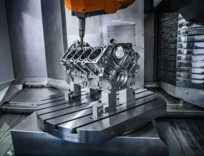
A part qualifies as complex geometry when it has features a tool can’t reach from a single fixed orientation — curved blade surfaces, deep angled pockets, or undercuts that would require a second or third setup on standard equipment. Machining these features accurately usually requires 5-axis machining, where the cutting tool and part can move relative to each other across five simultaneous axes instead of three, reaching angles a 3-axis mill physically cannot.
Complex Geometry Machining vs Standard 3-Axis Machining
| Factor | Complex Geometry (5-Axis) | Standard 3-Axis Machining |
|---|---|---|
| Tool access | Multi-directional, simultaneous angles | Top-down only |
| Setups for curved/undercut features | Single or few | Multiple manual re-fixtures |
| Positional accuracy risk | Lower — fewer repositioning steps | Higher — error compounds per setup |
| Surface finish on curved features | Continuous, smoother as-machined | Stepped, often needs secondary finishing |
| Best fit | Impellers, gimbals, aerospace contours | Flat brackets, simple pocketed parts |
Materials, Tolerances & Lead Times for Complex Geometry Parts
Material choice affects how a complex shape holds up during multi-axis cutting, particularly on thin blade sections or deep, narrow features where rigidity matters more than on a simple block part.
| Material | Common Complex Geometry Application | Typical Tolerance | Standard Lead Time |
|---|---|---|---|
| Aluminum 6061 / 7075 | Impellers, drone frames, robotics housings | ±0.013 mm | 5–8 days |
| Titanium Ti-6Al-4V | Aerospace structural contours | ±0.005 mm | 7–10 days |
| Stainless 17-4PH / 316L | Medical instrument curved components | ±0.005 mm | 6–9 days |
| Brass / Bronze | Complex connector and RF geometry | ±0.008 mm | 5–7 days |
| PEEK | Lightweight curved components for medical and aerospace | ±0.025 mm | 6–8 days |
Practical Examples Across Industries
- Aerospace & UAV components: turbine impellers and gimbal housings with curved blade geometry machined from solid aluminum or titanium billet.
- Robotics & automation: compound-angle joint housings and cable routing components that would require multiple setups on 3-axis equipment.
- Medical devices: anatomically curved instrument components requiring smooth, continuous surfaces without secondary polishing.
- Automotive & EV: aerodynamic brackets and sensor mounts with angled mounting faces machined in a single setup.
- Electronics & RF components: waveguide and connector housings with internal curved cavities inaccessible to standard tooling.
Why Setup Count Matters More Than Most Buyers Realize
Every time a part gets unclamped and repositioned on a 3-axis mill, a small amount of positional error gets introduced — usually invisible on a caliper check, but often enough to throw off bore alignment or angular tolerance on a part with several interrelated features. Complex geometry parts machined in one or two setups on 5-axis equipment avoid that compounding error entirely, which is why a part that looks similar in cost between two shops can perform very differently once it’s actually assembled.
How to Specify Complex Geometry Machining Correctly
Flag which surfaces are functional (sealing faces, bearing bores, mating contours) versus cosmetic, since that determines where tight tolerance actually needs to be held. Confirm the shop runs 5-axis equipment in-house rather than subcontracting the hard features, and check whether CNC milling and CNC turning capacity is available for the simpler features on the same part, avoiding a second vendor for a single component. Review quality certifications such as ISO 9001, and check case studies or Kintec’s own 5-axis machining guide for real examples of complex parts produced, not just capability claims.
FAQ: Complex Geometry Machining
What kind of parts need complex geometry machining?
Parts with curved blade surfaces, undercuts, compound angles, or features accessible only from multiple directions — impellers, gimbal housings, and aerodynamic brackets are common examples.
Does complex geometry machining always require 5-axis equipment?
Not always, but most genuinely complex shapes are impractical or inaccurate to produce with repeated 3-axis setups, making 5-axis the more reliable and often more cost-effective choice.
What tolerance can be held on complex geometry parts?
Critical features typically hold ±0.005–0.013 mm depending on material, with the specific tolerance flagged on functional surfaces rather than the entire part.
How much longer does complex geometry machining take compared to simple parts?
Lead times run roughly 5–10 days depending on material and feature complexity, longer than simple 3-axis parts due to programming time and slower multi-axis toolpaths.
Get Your Complex Geometry Machining Quote
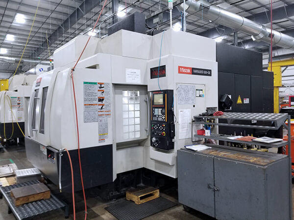
Kintec runs 5-axis machining in-house alongside milling, turning, and Swiss capability, so complex parts don’t get split across multiple suppliers.
- ✅ 5-axis machining for curved, undercut & compound-angle geometry
- ✅ Tolerances to ±0.005 mm on critical features
- ✅ No minimum order — prototype from 1 piece
- ✅ ISO 9001:2015 certified facility
- ✅ 24-hour quote turnaround
👉 Send your drawing now and get a free complex geometry machining quote in 24 hours.