A part that’s off by a few microns doesn’t usually fail on the machine — it fails three weeks later, in an assembly, on the other side of the world, after tooling and freight are already sunk into it. That’s the real cost of getting precision CNC components wrong: not the machining bill, but everything downstream of a bore that won’t press-fit or a mating face that won’t seal. This guide walks through where precision actually gets won or lost — tolerance selection, material behavior, process choice, and inspection — so engineers and sourcing managers can specify with confidence instead of hoping the vendor gets it right.
Why “Good Enough” Tolerances Cost More Than You Think
Most tolerance failures aren’t dramatic. A feature that’s 0.02 mm out of spec doesn’t look wrong on a caliper reading — it just doesn’t seat right, and nobody notices until final assembly or, worse, field return. The problem compounds because one loose dimension rarely stays isolated.
| Tolerance Deviation | Typical Consequence | Cost Impact |
|---|---|---|
| 0.01–0.02 mm | Increased assembly friction, inconsistent fit | Moderate — rework at assembly |
| 0.02–0.05 mm | Press-fit failure, seal leakage | High — scrapped parts, delayed builds |
| 0.05 mm+ | Component won’t assemble at all | Critical — full batch rejection |
A single loose dimension on a bracket or housing can cascade into a sealing failure, a misaligned bearing, or a sensor that reads inconsistently — and by the time that shows up, it’s rarely just one part. This is why engineering tolerance has to be treated as a functional spec, not a formality on the drawing.
What Precision Machining Actually Costs You (and What It Saves)
Sourcing managers often compare quotes on price per part without accounting for what happens upstream and downstream of that number. CNC machining, die casting, and stamping all carry very different cost profiles once tooling, scrap rate, and rework are factored in.
| Cost Component | CNC Machining | Die Casting | Sheet Metal Stamping |
|---|---|---|---|
| Tooling investment | None to minimal | High — hard tooling required | High — progressive dies |
| Best production volume | Prototype to mid-volume | High volume only | Very high volume, simple geometry |
| Achievable tolerance | ±0.005–0.013 mm | ±0.1–0.3 mm | ±0.1–0.2 mm |
| Design change cost | Low — reprogram, no re-tool | High — new mold required | High — new die required |
For projects where the design might still shift, or where volumes don’t justify a mold, prototype and preproduction machining avoids sinking tooling cost into a design that isn’t locked yet. Once volume is confirmed, high-volume production capability carries the same tolerance forward without a process change.
How to Get a Flawless Surface Finish Without Adding a Second Vendor
Surface finish gets treated as a cosmetic afterthought until it isn’t — a rough bore drags on a shaft, a coarse seal face leaks, a mismatched anodized batch gets rejected on a visual inspection nobody warned you about.
| Machining Parameter | Effect on Finish | General Guidance |
|---|---|---|
| Spindle speed | Higher speeds reduce visible tool marks | Maximize within tool and material limits |
| Feed rate | Slower feed produces a smoother path | Minimize on final finishing pass |
| Depth of cut | Light finishing passes reduce induced stress | Use a shallow final pass on critical faces |
Post-processing closes the gap between “machined” and “finished.” A polished or lapped surface behaves differently under load and in a seal than an as-milled one, which is why finish should be specified as a functional requirement on critical faces, not left to whatever the shop defaults to.
| Finishing Method | Best For | Typical Result |
|---|---|---|
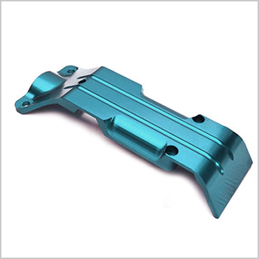
| Bead blasting / anodizing | Cosmetic and corrosion-resistant finishes | Consistent matte or color finish |
| Mechanical polishing | Sealing surfaces, cosmetic parts | < 0.2 µm Ra |
| Passivation | Stainless steel corrosion resistance | Improved surface passivity, no visual change |
Material Pitfalls That Derail Precision CNC Projects
Picking a material off a strength chart without accounting for how it actually behaves under a cutting tool is one of the most common — and most expensive — mistakes in sourcing precision components.
| Material | Key Advantage | Common Pitfall |
|---|---|---|
| Aluminum | Fast to machine, excellent strength-to-weight | Softer grades gall and build up on the tool |
| Titanium | Exceptional strength-to-weight, corrosion resistance | Poor heat dissipation accelerates tool wear |
| Stainless Steel | Outstanding corrosion and wear resistance | Work-hardens quickly under inconsistent cutting |
| Brass | Excellent machinability, attractive finish | Grade selection affects both strength and corrosion life |
| Copper | Unmatched electrical and thermal conductivity | Softness makes tight tolerance harder to hold |
The right call usually isn’t the material with the best spec-sheet number — it’s the one that machines predictably at the tolerance the part actually needs. Kintec’s material properties guide and material comparison reference walk through that trade-off in more depth for each alloy family.
Why 5-Axis Machining Changes What’s Possible on Complex Parts
Parts with angled bosses, deep pockets, or curved surfaces used to mean multiple setups on a 3-axis mill — and every re-fixture is a chance for error to creep in.
| Capability | 3-Axis Machining | 5-Axis Machining |
|---|---|---|
| Tool access | Limited, top-down only | Multi-directional in one setup |
| Setups required for complex parts | Multiple, manual re-fixturing | Single or few |
| Tolerance stack-up risk | Higher — each setup adds error | Lower — fewer repositioning steps |
| Surface finish on curved features | Stepped, often needs polishing | Continuous, smoother as-machined |
Completing a part in one or two setups instead of four or five doesn’t just save time — it removes the accumulated positioning error that shows up as inconsistent bore location or angular misalignment on the finished part. 5-axis machining is where that difference actually shows up on the inspection report.
How to Cut Lead Time Without Cutting the Corners That Matter
Speed and precision aren’t naturally at odds — most of the time lost budget in a rushed quote isn’t cut from machining time at all, it’s cut from planning and inspection, which is exactly where it costs the most later.
| Strategy | Primary Goal | Effect on Lead Time |
|---|---|---|
| Early DFM review | Catch design issues before cutting starts | Prevents costly redesigns mid-run |
| Right-sized tooling | Match tooling to material and geometry | Reduces cycle time per part |
| Batching setups | Minimize machine downtime between jobs | Improves throughput on repeat orders |
For projects where volume isn’t locked in yet, low-volume production keeps lead time short without forcing a commitment to a batch size that might not match final demand.
Design Rules That Keep Precision Parts On Budget
A lot of what makes a part expensive to machine has nothing to do with tolerance — it’s wall thickness, pocket depth, and corner geometry that dictate how many passes, how much tool wear, and how much risk of warping a part carries.
| Material | Recommended Minimum Wall Thickness |
|---|---|
| Aluminum | 0.8 mm |
| Stainless steel | 1.0 mm |
| Engineering plastics (PEEK, Delrin) | 1.5 mm |
Internal corners deserve the same attention. A sharp internal corner forces a slower, specialized tool path; a slightly larger radius machines faster and cheaper without changing how the part functions in most applications.
| Internal Corner Radius | Machining Speed | Relative Cost |
|---|---|---|
| 0.5 mm | Slow | High |
| 1.0 mm | Moderate | Moderate |
| 2.0 mm+ | Fast | Low |
How to Verify Dimensional Accuracy Before Parts Reach Assembly
A caliper reading tells you a part is close. It doesn’t tell you a bore is round, a face is flat, or a hole is exactly where the drawing says it should be — and those are the dimensions that actually cause assembly failures.
| Verification Method | Measurement Scope | Best Used For |
|---|---|---|
| Manual calipers/gauges | Basic length, width, diameter | Non-critical dimensions |
| CMM inspection | Complex profiles, position, flatness, true position | Critical, function-driving features |
Drawings that specify GD&T rather than just linear dimensions give a CMM something concrete to verify — form, orientation, and location, not just size. Confirming a supplier’s quality certifications and inspection process before committing a critical drawing is cheaper than finding out at assembly that a “close enough” part wasn’t.
When Precision CNC Machining Beats Die Casting for Critical Housings
Die casting wins on unit cost at high volume — but for parts where a sealing surface or vacuum-tight fit is non-negotiable, the process itself introduces risks that machining from solid billet avoids entirely.
| Factor | Die Casting | CNC Machining |
|---|---|---|
| Typical tolerance | ±0.1–0.3 mm | ±0.005–0.013 mm |
| Porosity risk | Present — trapped gas voids possible | None — solid billet |
| Post-processing need | Often required to hit spec | Minimal on precision features |
| Design change cost | New mold required | Reprogram only |
For applications like sealing housings or optical mounts, that difference in process integrity is the difference between a part that works and one that fails intermittently in the field. Kintec runs both processes — custom die casting for high-volume simple geometry, and precision machining for everything that needs to hold a tighter line.
Practical Examples: Where Precision CNC Components Actually Get Used
- Aerospace structural fittings: titanium brackets machined to ±0.005 mm, verified by CMM against documented inspection reports.
- Medical instrument components: passivated stainless steel parts with tight bore and concentricity tolerances for surgical devices.
- Robotics gearbox housings: aluminum housings with bearing bores held to ±0.01 mm to control backlash.
- Electronics connector components: Swiss-turned brass pins requiring sub-0.01 mm concentricity for reliable mating.
- Automotive sensor housings: low-volume aluminum parts machined ahead of tooling investment for the full production run.
FAQ: Precision CNC Components
What tolerance range actually counts as “precision” machining?
Anything tighter than ±0.05 mm is generally considered precision work; critical aerospace and medical features commonly land in the ±0.005–0.013 mm range.
Does tighter tolerance always mean higher cost?
Only on the features that are actually held tight. Applying precision tolerance selectively to functional dimensions, rather than the whole print, keeps cost proportional to what the part needs.
Which materials hold precision most consistently across a production batch?
Stable, fine-grain materials like stainless steel, titanium, and brass hold dimensional control more predictably than softer or more thermally reactive materials.
Is there a minimum order for precision machined parts?
No. A reputable CNC shop quotes both a single prototype and a full production run without requiring a minimum order.
Get Your Precision CNC Components Quote
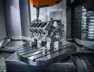
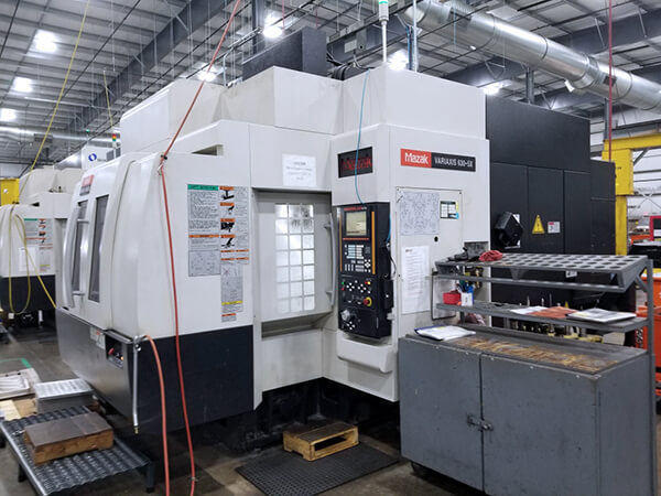
Kintec machines precision CNC components using CNC milling, turning, 5-axis, and Swiss machining, backed by CMM inspection on every critical feature.
- Tolerances to ±0.005 mm on critical features
- CMM inspection reports and material certs on request
- No minimum order — prototype from 1 piece
- ISO 9001:2015 certified facility
- 24-hour quote turnaround
👉 Send your drawing now and get a free precision CNC machining quote in 24 hours.